- Categories
- Categories
- New & Hot Products
- Engine Swap Parts
- Categories / Engine Swap Parts
- Also in Engine Swap Parts
- Accessory Drive Brackets and Kits
- Exhaust Systems
- Gen III Hemi Swap Systems
- Mounts and Crossmembers
- Swap Accessories
- View All
- Marine and Powersports
- Categories / Marine and Powersports
- Also in Marine and Powersports
- Personal Watercraft
- Small Engine
- View All
- Air & Fuel Delivery
- Categories / Air & Fuel Delivery
- Also in Air & Fuel Delivery
- Air Cleaners
- Air Scoops
- Cold Air Intake
- Fuel System Kits
- Fuel Tanks and Fuel Cells
- HydraMat
- View All
- Exhaust
- Nitrous
- Categories / Nitrous
- Also in Nitrous
- Bottles and Accessories
- Controllers and Accessories
- Direct Port Systems
- Distribution Blocks, Filters, Adapters and Fittings
- Electrical and Wiring
- Fuel Pumps and Regulators
- Gauges
- Hose Lines and Tubing
- Intercooler Sprayers
- Microswitch and Solenoid Mounting Brackets
- NOS Jets
- Nitrous Blowdown Hoses and Tubes
- Nitrous Plates
- Nozzles
- Purge Kits
- Refill Kits and Components
- Solenoids and Solenoid Service Parts
- Tools
- View All
- Apparel & Collectibles
- Categories / Apparel & Collectibles
- Also in Apparel & Collectibles
- Backpacks
- Banners
- Clocks
- Decals
- Diecast
- Drinkware
- Face Masks & Gaiters
- Headwear
- Hitch Cover
- Hoodies
- Jackets
- Ladies Apparel
- Literature
- Metal Signs
- Misc
- Pet Accessories
- Polo Shirts
- Shop Shirt
- Sunglasses
- Tote Bags
- Youth Apparel
- View All
- Exterior
- Categories / Exterior
- Also in Exterior
- Convertible Tops and Components
- Decklid Panels
- Doors
- Fenders
- Firewall, Cowl, and Front Unibody
- Floor Pan and Frame
- Fuel Doors
- Graphic Kits
- Grilles
- Hood
- Lighting
- Mini Tub Kits
- Plate Frames and Accessories
- Quarter Panels
- Radiator Supports
- Rear Spoilers
- Rocker Panel
- Roof Panel
- Trim and Moldings
- Truck Bed & Parts
- Truck Cab & Parts
- Valances
- Weatherstrip
- Window and Windshield
- View All
- Off-Road
- AC and Heating
- Categories / AC and Heating
- Also in AC and Heating
- Controls and Cables
- Filler and Delete Panels
- Heater Box and Hoses
- Heater Core
- View All
- EV Conversions
- Categories / EV Conversions
- Also in EV Conversions
- Conversion Brackets and Accessories
- Displays
- High Voltage Contactors
- High Voltage Disconnects
- Power Distribution (PDU)
- Sensors, Connectors, and Accessories
- Vehicle Controls (VCU)
- Wiring Harnesses
- View All
- Plumbing AN Fittings and Hose
- Categories / Plumbing AN Fittings and Hose
- Also in Plumbing AN Fittings and Hose
- Adapters
- All Hose Groups
- Application Specific Parts
- Catch Tanks
- Fuel System Components
- Hose Ends
- Hose Protection, Sleeving & Clamps
- Mr Gasket Push-On
- Mr Gasket Swivel
- Oil & Cooling Systems
- Plumbing Tools
- Power Steering
- Premade Hoses
- Seals
- Super Stock
- Ultra Flex
- UltraPro
- Valves
- Weld-ons and Fill Caps
- View All
- Brakes
- Fasteners and Hardware
- Categories / Fasteners and Hardware
- Also in Fasteners and Hardware
- Quarter Turn Fasteners
- Safety Wire
- Transmission and Drivetrain
- Wheel and Tire
- View All
- Restoration
- Categories / Restoration
- Also in Restoration
- Air Conditioning and Heating
- Air and Fuel Delivery
- Books, Manuals & Brochures
- Brakes
- Bumper
- Convertible Tops and Components
- Cooling
- Decals Labels & Tags
- Electrical
- Engine & Transmission Mounting
- Exhaust
- Fender Covers
- Fuel Tanks & Components
- Ignition
- Lamps & Lighting
- Longbed to Shortbed Conversion Kits
- Radios & Stereos
- Suspension & Steering
- Trailer Hitches
- Transmission & Drivetrain
- Weatherstrip & Rubber
- Wheels & Accessories
- Windows & Windshield
- Wood Bed Floor and Trim
- View All
- Carburetors
- Gaskets
- Safety Equipment
- Categories / Safety Equipment
- Also in Safety Equipment
- Aprons
- Arm Restraints
- Chest and Rib Protectors
- Cleaners
- Drag Parachutes
- Equipment Bags
- Head and Neck Restraints
- Seats
- Shifter Boots
- Shoes
- Tow Straps
- Undergarments
- Window Nets
- Youth
- View All
- Cataclean
- Categories / Cataclean
- Gauges and Gauge Accessories
- Categories / Gauges and Gauge Accessories
- Also in Gauges and Gauge Accessories
- Gauge Accessories and Harnesses
- Gauge Adapters and Fittings
- Shift Lights
- Tach Adapters
- View All
- Suspension & Chassis
- Categories / Suspension & Chassis
- Also in Suspension & Chassis
- Air Ride
- Body Mounts and Hardware
- C-Notch Kits
- Driveshaft Safety Loops
- Front Drop Axles & Kingpins
- Hitches and Towing
- Leveling and Lift Kits
- Longbed to Shortbed Conversion Kits
- Roll Cage Kits
- Shocks and Struts
- Springs & Bumpstops
- Strut Tower and Chassis Braces
- Sway Bars and Components
- Traction Bars and Components
- View All
- Cooling
- Ignition
- Tools, Shop Equipment & Chemicals
- Categories / Tools, Shop Equipment & Chemicals
- Also in Tools, Shop Equipment & Chemicals
- Diagnostic Tools
- Engine Tools
- Extra Long Fender Covers
- Fender Covers
- Fluid Tools
- Front End Covers
- Hand Tools
- Jumbo Fender Covers
- Oils, Fluids, & Additives
- Paint & Dye
- Shop Tools
- Trailer Tools
- View All
- Data Acquisition
- Categories / Data Acquisition
- Also in Data Acquisition
- Cables
- Modules
- Power Distribution Modules
- Sensors
- Sensors With Modules
- Wiring Accessories
- View All
- Intake Manifolds
- Categories / Intake Manifolds
- Carbureted Intake Manifolds
- Carburetor and Manifold Combos
- EFI Intake Manifolds
- Installation Parts and Accessories
Also in Intake Manifolds- Roots Supercharger Intake Manifolds
- View All
- Transmission & Drivetrain
- Categories / Transmission & Drivetrain
- Also in Transmission & Drivetrain
- Internal Components
- Rear Axle & Differential
- Transmission Controller
- Transmission Coolers
- Transmission Mounts
- Transmission Pans and Dipsticks
- Transmission Swap Parts
- Transmissions
- View All
- EFI - Fuel Injection
- Categories / EFI - Fuel Injection
- Also in EFI - Fuel Injection
- AEM EFI
- Atomic EFI
- EFI Distributors
- EFI Fuel System Components
- Gauges and Displays
- Harnesses
- Hilborn EFI and MFI Systems
- Hilborn Service Components
- Injectors
- Legacy EFI
- Modules and Sensors
- Terminator EFI
- Throttle Bodies
- Wiring Shop
- View All
- Interior
- Tuners and Programmers
- Categories / Tuners and Programmers
- Also in Tuners and Programmers
- Accessories
- Amp'd Throttle Booster
- Dinan Software-Tuning
- Inline Tuning Modules
- PCM
- View All
- Electrical
- Lighting
- Categories / Lighting
- Also in Lighting
- Bezels and Trim
- LED Light Bars
- LED Work Lights
- Marker and Signal Lamps
- Tail Lights
- View All
- Wheels and Wheel Accessories
- Categories / Wheels and Wheel Accessories
- Engine
- LS Power
- Categories / LS Power
- Also in LS Power
- EFI Components
- Engine and Transmission mounts
- Fuel Pump Regulator and Filter
- Fuel Tanks
- LS Accessory Drive Brackets and Kits
- LS Drivetrain
- LS Engine Components
- LS Gaskets
- LS Ignition Products
- LS Swap Oil Pans
- LS Swap Radiators
- LS Throttle Bodies
- LS Tools
- LS Valve Covers & Engine Appearance
- LS and LT Nitrous Systems
- View All
-
- Brands
- Brands
- ACCEL
- DiabloSport
- Holley RetroBright
- REKUDO
- ADS
- Dinan
- Hooker
- REV Wheels
- AEM
- Drake Muscle Cars
- Hooker BlackHeart
- Rocket Racing Wheels
- AEM EV
- Earl's
- Hurst
- Scott Drake
- Amp'd
- Edge
- Lakewood
- Simpson Motorcycle
- Anvil Off-Road
- Fender Gripper
- Legendary Wheels
- Simpson Racing
- APR
- Flowmaster
- Mallory
- Sniper
- B&M
- Flowmonster
- Mr. Gasket
- SPAL Fans
- Baer Brakes
- Flowtech Exhaust
- MSD
- Speartech
- Brawler
- Frostbite Cooling
- NOS
- Stilo
- Bright Earth
- Garrett Turbochargers
- ProConnect
- Street Fire
- Brothers Trucks
- Halibrand
- Proforged
- Superchips
- Carroll Shelby Wheels
- HANS
- Pulsar
- Weiand
- CataClean
- Hays
- Quick Fuel Technology
- White Box
- Classic Instruments
- Hilborn
- Quick Time
- XDR
- Demon
- HK Wheels
- Racepak
-
- Detroit Speed
- Holley
- RaceQuip
-
- DeWitts
- Holley EFI
- Range Technology
-
- Shop By Vehicle
- Shop By Vehicle
- Deals
Hilborn EFI and MFI technical support
- Home /
- Support /
- Fuel Injection /
- Hilborn EFI and MFI
See More
Tech Documents and Downloads
| Turbo Schematics |
|---|
|
8-CYLINDER TURBO SCHEMATIC
INSTALLATION SCHEMATIC OF A HILBORN FUEL INJECTOR FOR TURBOCHARGED ENGINE WITH 8-CYLINDERS & “P” VALVE |
|
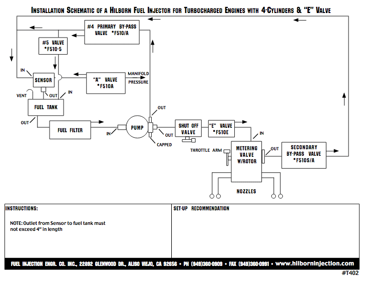
4-Cylinder Turbo Schematic
INSTALLATION SCHEMATIC OF A HILBORN FUEL INJECTOR FOR TURBOCHARGED ENGINE WITH 4-CYLINDERS & “E” VALVE |
|
VW TURBO SCHEMATIC
INSTALLATION SCHEMATIC OF A HILBORN FUEL INJECTOR FOR TURBOCHARGED VW ENGINE WITH 4-CYLINDERS & “E” VALVES |
| TPS Schematics |
|---|
|
HOLLEY TPS
Holley TPS Wiring Instructions |
|
FAST TPS
F.A.S.T. TPS Wiring Instructions |
OPERATING TIPS
These operating tips and suggestions are the result of experience gained by years of running under varied conditions.
- Due to the extreme clean-burning of finely atomized fuel, spark plugs generally take a long time to show any color. Do not change the mixture because of plug readings based only on a few laps. Pay more attention to the indications on the tops of the pistons, if visible, than to the plugs.
- If the system does not operate correctly, disconnect the nozzle hoses, remove nozzle caps and blow through the nozzles with air pressure. If this procedure does not solve the problem, we recommend sending the injector, fuel pump and by-pass valve to our factory for testing and/or repair. When returning the unit, please supply all pertinent information such as the cubic inch of the engine, the type of fuel being used (gas, alcohol, or percentage of nitro) and manifold pressure if supercharged.
- Do not allow running low levels of fuel in the tank as it will wash away from the pickup in the tank when the car is in the turns. The resulting gulp of air sucked into the system will give a momentary misfire in the engine. This is the first warning when running low on fuel.
- Avoid tampering with the adjustments continuously. The unit is factory set and ready to run as received. Simply install the injector, select the desired starting by-pass jet and go out and race.
- Shut the fuel off when the engine is not running to keep the nozzles from dripping. A shut-off valve should be installed on the outlet side of the fuel pump.
- When the car has been left standing with the engine hot, you may notice that the throttle has become a little tight. This is due to expansion of the aluminum casting as it picks up heat from the engine. When the engine is started, the fuel spray cools it down and the throttle will free up immediately.
- Extreme care should be taken to keep dirt from getting past the fuel filter and plugging a nozzle. Whenever the fuel lines are disconnected, tape up the openings immediately. Also watch for dirt in the threads of fittings when installing the pump and filter. Too much emphasis cannot be placed on the need for cleanliness.
FAQs
- Do I need to use a mechanical fuel pump with mechanical fuel injection or can I substitute an electric pump?Typically spinning at half engine speed, a mechanical pump increases system volume and pressure according to increases in RPM. The varying volume and pressure from the pump is tailored to fit the fuel demands of the engine, from idle to wide-open throttle, with the use of pills (jets), a barrel valve, and assorted bypass valves. Because of this, the constant pressure of an electric fuel pump is not suitable for mechanical fuel injection.Helpful?
- Which fuel pump should I run?The first digit of the serial number stamped (not cast) into HILBORN pump castings indicates the pump volume. The following list is a guide to help you select the correct pump size for your fuel requirements: PG150 series size #00 – Extremely small engines such as motocycles. size #0 – Medium size engines, 200″ to 360″, running gas or methanol. Use with carburetors or small turbo engines. size #S0 – (Super-0) Medium size engines, 360″ to 410″, running gas, methanol, or small amounts of nitro. size #1/2- Same as #S0, just a higher pump volume. size #1 – Large engines on gas and small amounts of nitro. Also for blown engines on gas, methanol, and small amounts of nitro. PG175 series size #2 – Large engines with high percentages of nitro and blown engines on methanol. size #4 – Very large engines, high percentages of nitro, and blown engines on nitro. PG250 series size #5 – Largest pump volume. Very large engines on nitro. Also for turbo or supercharged engines.Helpful?
- Other manifolds have a built-in plenum for the IAC, why doesn’t Hilborn?Our manifolds do not employ a built-in plenum which is popular today. We have found that this hybrid design reduces the primary attribute of increased cylinder fill of an IR manifold by exposing the laminar airflow to opposing pulses from other cylinders, negatively affecting power and low-speed drivability.Helpful?
- How much more power will I make?A common question but one with a varying answer. Depending on the induction system we replace, we have seen upwards of 100+ lb/ft and almost 100 horsepower with these torque increases much earlier in the curve. Although those numbers are not typical, we do generally see at a minimum, an increase of 30-40 hp and 45-55 lb/ft of torque. All applications will respond with a tremendous increase in throttle response and, more importantly, a substantial increase in engine acceleration rate.Helpful?
- How can I identify the rotation of my Hilborn fuel pump?Position the pump so the inlet is on your right and you are looking at the cover plate end of the pump. If the small dowel pin in the cover is at the top 12 o’clock position, it is a front cam drive rotation. If the pin is at the bottom 6 o’clock position, it is a belt drive or rear cam drive rotation.Helpful?
- How to change the rotation of the fuel pump?Remove the cover bolts and dowel pin. Move the pin 180 degrees to the opposite hole and replace the lid. Caution: Sometimes this change results in a tight pump. If this occurs, do not run the pump, but return it the factory for correction.Helpful?
- DO I REALLY NEED TO RUN THE POWER WIRES ALL OF THE WAY TO THE BATTERY? I’VE RUN A LARGE CABLE UPFRONT AND IT SHOULD BE JUST AS GOOD RIGHT?The battery is a natural capacitor making it capable of filtering unwanted signals from power lines. It is these unwanted signals that can interrupt the proper operation of the ECU causing drivability issues. But in order to receive the benefits of this filtering, the power wires from the ECU MUST go directly to the battery terminals and not to a master disconnect, fuse block, or junction block. Wiring that is not attached directly to the battery terminals is no longer filtered by the battery. It is highly recommended that the ECU be powered directly to the battery. NHRA/IHRA Safety Rules: A common misconception is that wiring the ECU directly to the battery will not allow the engine to be shut down with a master disconnect. This is not the case since it is the switched 12v line that turns the ECU off and on. The switched 12v line is typically installed after the master disconnect keeping the car within the NHRA/IHRA safety rules.Helpful?
- CAN I RUN ALCOHOL OR E85 WITH ELECTRONIC FUEL INJECTION?Yes, both types of fuel can be run with an EFI system. As a rule, alcohol is very corrosive, and unless you are prepared to constantly maintain your fuel system, we do not recommend it. At double, the volume over its gas counterpart, larger or even multiple injector sets, and possibly a mechanical fuel pump may be required. E85, on the other hand, has proven itself as a versatile fuel for performance street cars, whether naturally aspirated or blown. But much like alcohol maintenance is required especially if there are periods of inactivity with your vehicle. On average, E85 applications need a 30% increase in fuel volume requiring larger injectors and possibly fuel pump compared to gas applicationsHelpful?
- CAN I RUN AN O2 SENSOR WITH ZOOMIES?Yes, it can, but it may require open-loop operation of the ECU. At idle, cam overlap sucks fresh air into the exhaust and due to the short length of the pipe this will result in a false reading at the O2 sensor. Some tuning by “ear” will be required at idle, but typically as engine RPM increases the ECU closed loop function can be turned back on.Helpful?
- WHAT IS THE DIFFERENCE BETWEEN OPEN AND CLOSED-LOOP CONTROL?In Open loop, the ECU uses information from user-defined inputs, such as the fuel table, to set the injector duty cycle, and will not automatically correct to match your target air-fuel ratio. In Closed-loop, the ECU will monitor the A/F ratio and automatically adjust the injector duty cycle in order to meet the target A/F ratio. However, one must still tune the fuel table to keep the correction percentage as low as possible for a smooth transition from one cell to the next.Helpful?
- Do your systems self learn?Yes, mostly. We have found Holley’s self learn to be very robust and active but it has certain requirements for it to be active. Learning will not be active under throttle movement or fast MAP sensor movement. An IR manifold has very fast MAP movement even during light throttle tip-in which relegates the learning to be most helpful at cruise and at wide-open throttle. Regardless of how aggressive the learning is, most applications will need some touch-up tuning with a laptop.Helpful?
- WHY CAN’T I GET RUBBER HOSES OR INDIVIDUAL METAL LINES AS FUEL LINES FOR YOUR EFI MANIFOLDS?Although at one time, we supplied fuel hoses instead of the fuel rail, we have discontinued doing so for several reasons. Primarily, it is a safety issue. With a hose type fuel supply, a cap is typically attached to the nozzle (fuel injector) with a simple spring clip that is locked into a plastic groove. This is far from being as secure as a fuel rail, and if for some reason the clip, cap, or groove fails, high-pressure fuel is sprayed into the engine compartment. The second reason is more mundane but quite important to the drivability of your EFI system. The fuel supply in your EFI system is a dynamic device in that when the nozzle opens to spray fuel we have initiated the movement of this fuel. When the nozzle closes, the fuel in the line continues to flow (an object in motion tends to stay in motion) crashing into the nozzle. Its’ resulting force pumps a pulse back up the line upsetting the rest of the fuel supply. Due to the smaller inner diameter of the hose, this pulse is magnified as it makes its way back and forth in the injector line, mixing in with the fuel supply, as fuel tries to get to the nozzle. This pulsing creates a condition when, at various times, the nozzle opens and there is a lack of fuel pressure, and other times excessive fuel pressure, resulting in poor fuel control. This can negatively affect part-throttle drivability along with other issues. EFI is all about fuel control, and we have better success with the built-in reservoir of a fuel rail that acts to dampen those reversion pulses. In this case, function over form.Helpful?
- Can I run an IAC Valve?On 8 stack applications using a MAP sensor, a second vacuum kit is recommended for correct engine operation using an IAC. Installation of the second vacuum kit is not available from Hilborn Fuel Injection. An IAC valve is NOT required for proper idle operation of your EFI system but, on the other hand, it is highly recommended for blown systems.Helpful?
- Is your injection streetable?Very! Combined with EFI technology, our fuel injectors offer superior drivability under all types of conditions associated with aftermarket street performance. Although they perform very well on the street, they are not “street legal” or suitable for emission controlled vehicles, so we recommend that you check your local laws first.Helpful?
- Isn’t the Hilborn manifold technology “old school”?In actuality, nothing could be further from the truth. When one examines the dynamic inside a common plenum manifold, it is easy to understand how the disruptive reversion pulses from adjacent cylinders slam into the columns of laminar flow, causing fuel to fall out of suspension and separate with the air. This affects low-speed torque, top-end power, and acceleration rate since the working fluid is supplied to the combustion chamber in a less burnable state and with reduced volume. On the other hand, the isolated runners of a HILBORN individual runner (IR) manifold completely eliminate these reversion pulses, allowing the working fluid to remain in laminar flow, generating tremendous airspeed which fills the cylinder for maximum power potential. In racing venues where IR manifolds are legal, they are the dominant induction system. Supercar manufacturers, including Ferrari and Maserati, use IR technology to build maximum potential for their street cars, proving that there is no better induction system for your application.Helpful?
- I don’t race, I’m more concerned with drivability. How does your system perform at low engine speeds?Although we have many performance advantages, it is our low-speed drivability that really shines. The same attributes that provide our mid and top end power advantages are also why we have excellent idle, throttle response, and part throttle drivability. Since we no longer have to worry about those disruptive reversion pulses, our manifold is the perfect choice for smooth part throttle cruising on the open road. We have found this to be true whether your engine is stock all the way to heavily modified engines with large camshafts.Helpful?
- Will your manifold remove my camshaft thump at idle?When the butterflies are correctly adjusted, the engine may not be as rough at idle as with a carburetor, but the camshaft thump will be very pronounced. The trade-off is a positive though, as there is a dramatic difference in low-speed throttle response, torque and acceleration rate easily making up for the slight difference in sound.Helpful?
- Why is your IR manifold better than others?Hilborn manifolds are bred from our racing heritage and are designed to make maximum power. Our manifolds are a true individual runner (IR) manifold and are not conversions, instead, they are engineered at the foundry level to accept the EFI components. We have also found that one size doesn’t fit all, so our manifolds are flexible enough to fit engines with unique heads and various deck heights. Also, we offer a choice of butterfly sizes that allows us to tailor the manifold to meet, or exceed, the power expectations of your engine without compromise to drivability. No one gives you more choices than Hilborn.Helpful?
- What is a true individual runner manifold?A true IR manifold is one where the individual throats are completely segregated from the adjacent throats, allowing the highest possible airspeed, for not only maximum efficiency but also low-speed drivability. It is fashionable today for other IR manifold manufacturers to incorporate a common plenum, making them a hybrid design, muting the advantages of an IR manifold (maximum power and torque, engine acceleration rate, and especially low-speed drivability associated with our tremendous cylinder fill) while at the same time, introducing the disadvantages of a common plenum manifold. The primary reason for this hybrid design is the use of an IAC valve. Since it is not feasible to build the plenum large enough to not be affected by the operation of the IAC, a reduction in resolution for the MAP sensor, along with a noticeable decrease in low-speed drivability, is experienced. A second reason for the hybrid style intake is, it is thought to eliminate the need to correctly synchronize the butterflies. Unfortunately, this is not the case as butterfly synchronization is also required for the hybrid designs.Helpful?
- Why do your manifolds produce more power than other IR EFI manifolds?With our true individual runner curved throat design, multiple bore sizes, and optional porting, no other induction system can make as much power as a Hilborn IR manifold. In most applications, it is the intake manifold that is the primary restriction of airflow but our IR manifolds remove a majority of this restriction allowing the engine to breathe and to make maximum power throughout the operating range. The most important facet of our IR manifold is a dynamic that is never discussed and that is engine acceleration rate. We are able to condition the air/fuel charge and optimize cylinder fill which makes the combustion process extremely efficient resulting in a dramatic increase in how fast the engine responds and accelerates.Helpful?
- What cam profile works best with your IR manifolds?When tuning in speed density, a camshaft that promotes the highest engine vacuum is typically employed with the use of a common plenum manifold. But this can be a compromise for some performance engine builds. With the isolation of the runners in our IR manifold, we can be more aggressive with camshaft selection, without reducing or eliminating resolution. We have numerous aggressive combinations running in speed density with perfect street manners.Helpful?
- What is an IAC valve and can I run one with a Hilborn IR manifold?An idle air control valve or IAC is easily described as an electrically controlled vacuum leak. It is not a sensor, instead, it’s defined as an actuator since the ECU controls it. This variable vacuum leak allows the ECU to help maintain the programmed idle speed. With Hilborn IR manifolds running in Speed Density (MAP sensor), a second vacuum kit is recommended for correct engine operation using an IAC. Installation of the second vacuum kit is not available from Hilborn Fuel Injection. An IAC valve is NOT required for proper operation of your EFI system but, on the other hand, it is highly recommended for blown systems, and is easily attached with a -8 hose.Helpful?
- Is installation of your IR manifold difficult?Hilborn manifolds can come as either a single piece or three-piece design depending on the application. Single piece manifolds install the same as any other intake, but the three-piece manifolds will require drilling and tapping of the lifter valley rail (or China rail) in order to bolt down the center valley plate. We can offer technical help for those who have an assembled engine for a clean and trouble-free installation. Regardless of manifold type, butterfly adjustments are required before the initial start and after warm-up for proper operation.Helpful?
- Do I need a return line?Yes, our injection systems require a return line.Helpful?
- Do I need to run a thermostat?We do recommend the use of a thermostat with all EFI applications. Due to some of our manifolds being multi-pieced, we include a remote thermostat housing in our kits to aid in the installation of a thermostat.Helpful?
- Do you have air filters for my application?We offer many filter applications, especially for the more popular injector manifolds. These include our billet aluminum ram tube air filter combinations, bootie and tube top filters along with bug domes. We also supply box style sprint car filters from K&N or R2C. Another option is ram tube seals; an economical way of attaching a filter base to the ram tubes, thus, allowing a custom filter box to be designed. View our catalog for more information on air filtration products.Helpful?
- Should I dyno test my system?We advise dyno testing to get the most out of your EFI unit. We prefer a chassis dyno, instead of an engine dyno, since all the subsystems (fuel system, ignition system, and injector) are installed on the car. A chassis dyno also allows you to work out part throttle tuning, saving the additional expense of two dyno sessions.Helpful?
- So how does an engine with one of your IR manifolds idle without an IAC valve?When used with a 4-barrel type common plenum manifold, an IAC valve is an integral part of controlling warm idle and decel rpm. This is due to the turbulence created in a common plenum manifold. A HILBORN IR manifold, on the other hand, does not have this disruptive turbulence providing very stable idle and deceleration characteristics even with large camshafts. Our manifolds reduce the roughness at idle dramatically, allowing idle speeds down in the 650-700 rpm range without adversely affecting the exhaust “hit” we all want.Helpful?
- Can I run my vacuum accessories?Yes, we provide a vacuum junction block for all of your vacuum accessories but they must be of the closed variety. Closed vacuum accessories include MAP sensor, brake booster, and transmission modulators. Open vacuum accessories including PCV valves and IAC valves are not recommended as they will reduce or eliminate resolution for the MAP sensor.Helpful?
- What is noise, electrical interference or EMI?EMI is short for Electromagnetic Interference and is also known as noise or electrical interference. All wiring exerts an electrical field that is best described as an invisible slinky around the wire that grows as the current is increased. EMI is when higher voltage wiring emits a larger slinky and it jumps into an adjacent wire, creating an unwanted signal. This creates a problem with all types of electronic equipment such as ECUs. The remedy is to keep high power wires separated from signal wires and to attach the power wires of the ECU directly to the battery. The battery offers a natural filter to absorb those unwanted EMI pulses.Helpful?
- I read that IR manifolds always pop out of the ram tubes and that it can’t be fixed. Is this the case?Popping out of the ram tubes typically indicates a lean misfire and is an issue that is easily remedied. In most cases, it is merely due to improper synchronization of the butterflies. The process of synchronization includes initial manifold adjustments and then fine-tuning with the use of a synchrometer. See our videos on both subjects below. These procedures are normally performed with the engine and manifold at operation temperature, so it is not uncommon to have some slight popping out of the ram tubes when the engine is cold. Another issue is improper design of the throttle linkage where the throttle arm, throttle stop and return spring are at different locations of the manifold, which results in twisting of the throttle shaft and popping. Ensure that the throttle arm, throttle stop, and return spring are all located at the same location as the manifold. Finally, adjustments to the Fuel Table or AE Fueling in the ECU may be required to eliminate popping. When an IR manifold is installed and tuned as recommended, popping out of the ram tubes is a non-issue.Helpful?
- How can I loosen a stuck barrel valve rotor?Use penetrating oil (such Kroil) to loosen the rotor. Once free, remove the rotor from the barrel valve and position it in a drill press. Lightly polish the rotor with 600 grit sandpaper. Clean and oil the barrel valve before reassembly.Helpful?
- WHAT IF THERE ISN’T A DYNO SHOP IN MY AREA?In most areas, we are able to recommend dyno shops that can expertly tune your EFI system. But if you want to tune your EFI system yourself, you will be able to use the data logging capabilities that both systems have to pin point where to fine-tune. The Holley system has a very robust self-tuning algorithm that is exceptional at part throttle and even wide-open throttle, but it will not tune every facet of an IR or blown system and will require final tuning with a lap top.Helpful?
- ARE YOUR SYSTEMS PLUG AND PLAY?Our EFI systems come with the correct connectors, pre-terminated for all the sensors except the TPS and IAC (if your system uses one). Detail schematics are provided to attach these two components or see the links below. We understand that most people do not want to fill the engine compartment with extra wiring, so we are able to offer tips and tricks that allow you to extend only the wiring needed into the engine compartment for that clean look. In order to achieve this, we will need to lengthen or shorten wires which will require basic soldering iron skills. Since every application is considered custom, it is impossible to provide a one size fits all wiring solution. For those with advanced wiring skills, unterminated harnesses are also available.Helpful?
- WILL I SEE A MILEAGE INCREASE?Yes! EFI allows finite fuel and sparks tuning at any rpm and load. Used in conjunction, one is able to maximize fuel economy without sacrificing performance. In some cases, customers have reported doubling their mileage over their previous carbureted application.Helpful?
- WHICH IS THE CORRECT MAP SENSOR FOR MY APPLICATION?All naturally aspirated applications need only a 1 bar sensor. Boosted applications will need a 2 bar or higher, depending on the boost pressure. Since 1 bar is equal to 14.7psi, then a 2 bar will handle boost up to 14.7psi, a 3 bar 29.4psi, and so on.Helpful?
- What distributor do I need?We feel the best input signal for any EFI system is a crank trigger but understand that not all applications can accommodate a crank trigger. A discrete hall effect type distributor would be the next best option and plug and play styles from Holley and FAST are available. Due to the potential for noise and operating concerns, we attempt to shy away if all possible from the MSD magnetic pick-up type distributors. For those that want the look of a magneto for their EFI system, HILBORN Fuel Injection is proud to offer a Joe Hunt Conversion EFI distributor. More than just a conversion, these hand-built distributors start out as brand new bodies which are then treated to a proprietary hall effect pick-up and rotor. This distributor was designed specifically for EFI applications eliminating signal issues that plagued converted magnetos. HILBORN Fuel Injection can supply all of your distributor and ignition needs. Please feel free to call our EFI Tech Line to discuss distributor options for your application.Helpful?
- DO I NEED TWO O2 SENSORS?Both systems have the ability to accommodate dual O2 sensors but come standard with one. One is typically all that is required for correct operation but certain high horsepower or racing applications may benefit from two. The FAST XFI will allow the second O2 to be data logged, but the ECU will only correct off of one when run in a closed loop. To run two O2 sensors with a Holley the Dominator ECU is required. It will also datalog both O2’s and can be programmed to correct off of either or an average of both.Helpful?
- WHAT IS THE DIFFERENCE BETWEEN SPEED DENSITY AND ALPHA N?The Alpha N tuning strategy uses input from TPS and RPM to set the fuel curve, while Speed Density uses a MAP sensor and RPM. A MAP sensor in essence is an electrically controlled device that reads engine vacuum to identify engine “load”. An engine’s fuel requirements are directly related to load and the corresponding RPM more so than the throttle angle input of Alpha N. Therefore, the ability to tune to the constant change in engine load via Speed Density is desirable compared to Alpha N.Helpful?
- WHAT CAM PROFILE WORKS BEST WITH THESE ECUS?Since Speed Density uses engine vacuum to identify load AND the greater the vacuum signal between the part throttle and wide open the better the resolution is for tuning, a camshaft that promotes the highest engine vacuum is typically employed. But can be a compromise for some performance engine builds. As cams become more aggressive we lose engine vacuum at idle and the allowable resolution this signal offers. This is all true for a common plenum MPI injection system. But with a HILBORN IR manifold, we eliminate the reversion pulses that negatively affect the low speed and idle vacuum allowing the engine build to dictate the cam specifications, not the EFI system. So pick the camshaft that works best for your application and we’ll do the rest.Helpful?
- WHAT IS THE DIFFERENCE BETWEEN A WIDEBAND AND NARROW BAND O2 SENSOR?A narrow band O2 sensor can only correctly measure the stoichiometric air-fuel ratio. For gas, this ratio is 14.7 to 1, but this air-fuel ratio is not ideal for all applications. Since the ability to measure a specific air-fuel ratio other than 14.7 to 1 accurately with a narrow band O2 sensor is not possible, a wideband O2 sensor is employed. This type of sensor can accurately measure air-fuel ratios from 8 to 1 up to 16 to 1 and is preferred over the narrow band. Both ECUs offered to use a wideband O2 sensor.Helpful?
- WHAT DOES THE SELF LEARNING ACTUALLY DO?The job of a tuner is to not only find the ideal air-fuel ratio and timing curve but to also tune the fuel table or map. The fuel table has numerous cells that call out the fuel supply to the injectors and it is the tuner’s job to not only eliminate as much of the O2 correction as possible but to ensure that there is a smooth transition from cell to cell. The Holley self learn builds a background fuel table with corrections values for the main table in order to achieve the air-fuel ratio inputted and to keep the cell transition smooth. It is a tremendous technology but still imperfect especially when used with an IR system.Helpful?
- WHAT IF I’M NOT VERY COMPUTER SAVVY?The windows based software of both systems is much easier to learn and use compared to systems of yesterday. To get you started, we supply a custom base start-up calibration and go over the details. Our tech support is just one phone call away and we can walk you through any start-up issues you might have. Unlike our competitors, we do not charge for this service. Our technicians are unable to remotely tune your system for you, instead, we can supply tips on tuning technique so you can have the confidence to make the changes you want. However, if you are interested in a top-notch tuning service, ask us for details about Hilborn Fuel Injection’s on-site tuning program.Helpful?
- HOW DO THESE ECUS WORK?Simply put they use inputs from the O2, air, coolant, and MAP sensors and then determine the correct injector duty cycle in conjunction with inputs from the fuel table. The fuel table is user adjustable and is adjusted to provide a smooth transition from cell to cell as you accelerate.Helpful?
- WHAT IS AN IAC VALVE AND CAN I RUN ONE WITH A HILBORN IR MANIFOLD?An idle air control valve or IAC is easily described as an electrically controlled vacuum leak. It is not a sensor, instead, it’s defined as an actuator since the ECU controls it. This variable vacuum leak allows the ECU to help maintain the programmed idle speed. With Hilborn IR manifolds running in Speed Density (MAP sensor), a second vacuum kit is recommended for correct engine operation using an IAC. Installation of the second vacuum kit is not available from Hilborn Fuel Injection. An IAC valve is NOT required for proper operation of your EFI system but, on the other hand, it is highly recommended for blown systems, and is easily attached with a -8 hose.Helpful?
- HOW MANY CFM DOES YOUR IR MANIFOLD FLOW?A very common question! CFM ratings have been all the rage for quite some time, but it is only one small tool used in engine development. Since an engine is a dynamic device, using just one facet, such as CFM, without considering airspeed, can lead to an incorrect conclusion about a product. In most cases, intake manifolds typically don’t have a CFM rating as they are an extension of the cylinder head. Since a Hilborn injector functions as an intake, we are unable to provide any type of usable flow numbers. Instead, we base maximum performance on the size of the butterfly.Helpful?
- HOW TO AVOID CORROSION ON MAGNESIUM CASTINGSDue to the very reactive nature of magnesium in the presence of water or methanol, it is extremely important to keep the injector casting dry! Do not allow liquids to stand in the injector overnight. Both magnesium and aluminum injector systems should be kept clean. After racing, remove nozzles and blow out the entire unit and nozzle chamber with air.Helpful?
- Can I run a HILBORN EFI injector on a street car? What about a mechanical injector on the street?Because of EFI (electronic fuel injection), the Hilborn Injector has become the favorite choice for many types of motorsport enthusiasts that enjoy driving their cars on the street. This ranges from show cars that drive 500 miles a year to street rodders driving 35,000+ miles a year and everyone in-between. The joining of EFI and a Hilborn injector has produced what we feel is the ultimate induction system for any show car or street rod. We took the neck-snapping throttle response, the increased torque, and power, and the awesome engine acceleration common to a Hilborn Injector, controlled the fuel with EFI and found we had an unbeatable combination of calm drivability and unmatched performance. But the best was yet to come. We found that our manifold design, which removes the distribution concerns associated with a common plenum, allowed even the most aggressive engines to have extremely good part-throttle manners, while still retaining their aggressive exhaust note. Yes, that’s right, our race-inspired manifolds actually promote part throttle drivability. This would be our most important benefit since you spend most of your time at part-throttle in a street car.Helpful?
- Can I run a mechanical fuel injector on the street?A Hilborn mechanical injector is classified as a constant flow system and was designed to operate at WOT under load. As a constant flow system, pressure and volume are controlled by the main jet, or pill, along with pump speed (engine rpm) and nozzle size. The barrel valve, which controls idle fuel and transitional fuel from idle to WOT, can be compared to a ball valve much like the one that turns off the water in your house. The basic design and lack of fuel control of a barrel valve does not allow us to control the fuel at part throttle especially no-load part throttle. If you consider the fact that an engine’s fuel requirements are based directly on load, and that we can have many different loads at different rpms all at the same throttle angle, the lack of fuel control for street applications becomes apparent. A mechanical system does not employ enough fuel control in the operating range where you drive your street car and, therefore, is not recommended for street use. Of course, we have all heard the stories of mechanical systems working on the street but few if any actually worked correctly. The use of a dial-a-jet, additional bypass valves, and home center ball valves have all been used to provide fuel control for adequate street use, but fall far short of the fuel control required as part throttle load is constantly changing. The constant manual adjustments needed, as one guesses the current fuel requirements of the engine, leaves very little time to actually drive the car and, at best, is incredibly inaccurate. Blown applications appear not to be as affected by the lack of fuel control of mechanical injection, possibly due to the load placed on the engine to drive the blower, but is still not recommended for those looking for the best all-around drivability. The use of alcohol helps because of its large tune-up window, but fails to provide drivability due to loading up, mileage (in gallons to the mile), and severe oil dilution. Claims from those that run injected engines on stands or dyno’s stating they can make mechanical injection streetable, are unable to simulate a fraction of the different part throttle load scenarios your engine will see, nor provide the required fuel control. Interestingly enough, engineers have devised a way to electrically control these valves and bypasses… it’s called electronic fuel injection.Helpful?
- Can I convert my old mechanical unit?Although it is possible to convert your old Hilborn Injector to EFI, we have found that after spending the time and money required to accomplish this, it makes better financial sense to buy a new injector already set up for EFI. We’ve redesigned our original castings at the foundry level to accept all the necessary EFI components, which in the long run, can save you money by eliminating costly re-machining for conversion. Because of this, we do not offer machining conversion services at Hilborn Fuel Injection. However, most blown mechanical fuel injectors, whether scoop or hat style, can be easily converted to EFI.Helpful?
- What is required to synchronize the butterflies?We understand how critical butterfly adjustments are in order to realize the low-speed benefits you will receive with an IR manifold. We have developed techniques for butterfly adjustments and open source this information on our web site, see Synchrometer Tuning Video. We also supply a synchrometer with every manifold as it is required tooling for correct butterfly synchronization.Helpful?
- Why are your fuel rails located outside on some applications?Most of the manifolds in the Hilborn line are a curved throat design. This design, based on racing experience, allows the air to transition smoothly into the intake runner to help generate maximum power but affords very little room on the inside for fuel rail installation. Outside placement of the fuel rails also allows our injector nozzle bosses to be raised in the throat and situated to spray the fuel into the wall. This process conditions the fuel by smashing it into a smaller droplet allowing it to enter the air stream in a more burnable state. This also helps the fuel to pick up heat off the wall to start the expansion process, providing an extremely quick response in the combustion chamber for a tremendous increase in acceleration rate. We have found this process to be far superior to spraying the fuel directly onto the intake valve which promotes a larger fuel droplet and a reduction in combustion chamber response.Helpful?
- How many CFM does your IR manifold flow?A very common question! CFM ratings have been all the rage for quite some time, but it is only one small tool used in engine development. Since an engine is a dynamic device, using just one facet, such as CFM, without considering airspeed, can lead to an incorrect conclusion about a product. In most cases, intake manifolds typically don’t have a CFM rating as they are an extension of the cylinder head. Since a Hilborn injector functions as an intake, we are unable to provide any type of usable flow numbers. Instead, we base maximum performance on the size of the butterfly.Helpful?
- Why can’t I get rubber hoses or individual metal lines as fuel lines for your EFI manifolds?Although, at one time, we supplied fuel hoses instead of fuel rail, we have discontinued doing so for several reasons. Primarily, it is a safety issue. With a hose type fuel supply, a cap is typically attached to the nozzle (fuel injector) with a simple spring clip that is locked into a plastic groove. This is far from being as secure as a fuel rail, and if for some reason the clip, cap, or groove fails, high-pressure fuel is sprayed into the engine compartment. The second reason is more mundane but quite important to the drivability of your EFI system. The fuel supply in your EFI system is a dynamic device in that when the nozzle opens to spray fuel we have initiated the movement of this fuel. When the nozzle closes, the fuel in the line continues to flow (an object in motion tends to stay in motion) crashing into the nozzle. Its’ resulting force pumps a pulse back up the line upsetting the rest of the fuel supply. Due to the smaller inner diameter of the hose, this pulse is magnified as it makes its way back and forth in the injector line, mixing in with the fuel supply, as fuel tries to get to the nozzle. This pulsing creates a condition when, at various times, the nozzle opens and there is lack of fuel pressure, and other times excessive fuel pressure, resulting in poor fuel control. This can negatively affect part-throttle drivability along with other isues. EFI is all about fuel control, and we have better success with the built-in reservoir of a fuel rail that acts to dampen those reversion pulses. In this case, function over form.Helpful?

 Get help from other Gear Heads!

Product Registration
Extend your Warranty!
Extend your Warranty!

Warranties

Ask Our Experts!
1-866-464-6553
1-866-464-6553

Email A Technician
Back To Top